Have you ever stared at a tangled web of wires in your electrical panel and felt a surge of panic? You’re not alone. The world of electrical wiring can seem like a complex maze, especially when dealing with something as seemingly intricate as a 4-way switch. But fear not! This guide delves into the intricacies of 4-way switch wiring diagrams, demystifying this often-intimidating topic and empowering you with the knowledge to tackle any electrical project confidently.

Image: diagramweb.net
The 4-way switch, often referred to as a “traveler switch,” is a crucial element in multi-location lighting control. It allows you to turn a light fixture on or off from various points in a room or hallway, eliminating the need to walk back and forth to a single switch. But understanding the wiring behind this sophisticated system can be a hurdle for even the most seasoned DIY enthusiast. This comprehensive guide offers clarity, step-by-step explanations, downloadable diagrams, and practical tips to guide you through the maze of 4-way switch wiring.
Unraveling the Basics: Understanding the Mechanics
Before diving into the detailed diagram, let’s first grasp the fundamental concepts behind a 4-way switch system. Think of it like a relay race; each switch plays a crucial role in passing the electrical signal along to the next. Here’s a breakdown of the essential components:
- Power Source: This is the starting point, supplying the electrical current. Think of it as the runner holding the baton at the beginning of the race.
- Single-Pole Switch (SPST): This is the main switch that controls the light fixture. It acts as the final “switch” in the relay race, turning the light on or off.
- Three-Way Switch (3-Way): This is the first switch in the chain, enabling you to turn the light on or off from a specific location. It’s like the first runner, passing the baton to the next.
- Four-Way Switch (4-Way): This is the switch used to control the lights from additional locations beyond the initial two. It acts as a relay, passing the signal along to the next 4-way or a 3-way switch.
- Neutral Wire: This is an important safety and grounding component, ensuring proper electrical flow.
Decoding the 4-Way Switch Wiring Diagram
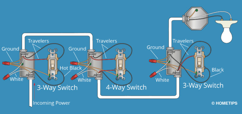
Let’s dive into the core of this guide: the wiring diagram. It’s the visual blueprint that helps you understand the connection between each component. Imagine you have a hallway with a light fixture you want to control from three locations. Here’s how you can use the diagram to comprehend the wiring:
1. Power Source to Single-Pole Switch: The first step is connecting the power source to the single-pole switch, acting as your main control point.
2. Single-Pole Switch to 3-Way Switch: The “hot wire” from the single-pole switch (also called the “traveler”) travels to one of the terminals on the first 3-way switch.
3. 3-Way Switch to 4-Way Switches: The “hot wire” then travels from the 3-way switch to one of the terminal screws on the first 4-way switch.
4. 4-Way Switch to 4-Way Switch: At each 4-way switch, the “hot wire” continues on to the next 4-way switch. It’s like the baton being passed from runner to runner, moving the signal along.
5. 4-Way to 3-Way Switch: From the final 4-way switch, the “hot wire” moves to the other terminal of the second 3-way switch.
6. 3-Way Switch to Light Fixture: The “hot wire” then travels from the second 3-way switch to the light fixture. Now, you have a complete circuit, allowing you to control the light from any of the switches.
Remember: It’s crucial to always consider safety when working with electrical wiring. Disconnect the power to the circuit before starting any work and ensure you’re familiar with basic electrical safety protocols.
Mastering the 4-Way Switch: Practical Tips and Insights
Understanding the diagram alone is not enough; you need practical tips to successfully install a 4-way switch system. Here are some insights from experienced electricians:
-
Wire Color Codes: Pay close attention to the color-coding of the wires. Black is generally used for hot wires, white for neutral wires, and bare copper for ground wires. While color codes can vary, always double-check with the wiring diagram to ensure correct connections.
-
Terminals: Each switch has specific terminals for connecting wires. A common mistake is connecting the traveler wires to the wrong terminals on the 4-way switches. Follow the diagram and check the switch’s markings to ensure accurate connections.
-
Testing and Troubleshooting: Always test your wiring after every step of the installation process. Use a voltage tester to confirm correct connections and ensure no unwanted short circuits.

Image: www.hometips.com
Download Your 4-Way Switch Wiring Diagram (PDF)
To help you visualize and grasp the intricate wiring connections, we’ve crafted a comprehensive wiring diagram in a downloadable PDF format. This diagram provides a clear and concise visual representation of the concepts we’ve discussed. Download it here: [Insert link to downloadable PDF].
4 Way Switch Wiring Diagram Pdf
Embracing the Power of Knowledge: Unlocking Electrical Mastery
This guide equips you with the knowledge to confidently tackle 4-way switch wiring projects. By understanding the diagram and following the tips from electrical professionals, you can master this seemingly complex system. Remember, safety always comes first. If you have any doubts or hesitations, seek assistance from a qualified electrician.
Take your electrical skills to the next level and embrace the power of knowledge! Share your experiences with 4-way switch wiring in the comments below and let’s create a community of confident DIY enthusiasts.


