
Remember that exhilarating feeling of watching the needle on your tachometer climb as you accelerate? It’s a thrill that every car enthusiast enjoys. But what happens when that needle refuses to move, or worse, displays inaccurate readings? A faulty tachometer can be a frustrating problem, but luckily, understanding the wiring diagram can help you troubleshoot and fix it. This article will delve into the intricacies of the Autometer Sport Comp Tach wiring diagram, guiding you through the process of understanding and interpreting it.

Image: wirelibrarytheissen.z19.web.core.windows.net
The Autometer Sport Comp Tach, a popular choice among performance-driven drivers, is known for its accuracy and responsiveness. However, even the most reliable instruments can require attention. Understanding the wiring diagram is crucial not only for troubleshooting but also for customizing the tachometer’s features, such as setting the redline or adjusting the illumination. Let’s embark on a journey of understanding the intricate world of Autometer Sport Comp Tach wiring.
Decoding the Autometer Sport Comp Tach Wiring Diagram
Understanding the Basics
The wiring diagram, essentially a schematic representation of the tachometer’s internal connections, plays a vital role in ensuring proper functionality. It reveals the intricate pathways through which electrical signals flow from the vehicle’s engine to the tachometer, enabling it to display the engine’s revolutions per minute (RPM). The diagram typically presents the tachometer’s terminals, each assigned a specific function and labeled accordingly. It also shows the corresponding color-coded wires that connect to each terminal, making it easier to identify and trace each wire’s pathway.
Essential Components of the Wiring Diagram
Let’s break down the key elements of the Autometer Sport Comp Tach wiring diagram. The diagram usually includes:
- Power Supply: The tachometer’s power supply is indicated by a designated terminal (often labeled “PWR”) and the corresponding wire that connects to the vehicle’s ignition system. This connection ensures that the tach receives power only when the ignition is turned on.
- Signal Input: The tachometer receives a pulsing signal from the vehicle’s engine. The signal input terminal is usually marked “SIG” or “IGN.” This terminal is connected to a wire that taps into the engine’s ignition system, typically the coil or the distributor.
- Ground: All electrical devices need a solid ground connection. The wiring diagram will show a terminal labeled “GND” or “GRD” and the associated wire that connects to the chassis or a negative terminal of the vehicle’s battery.
- Illumination: The tachometer’s illumination is controlled by a separate circuit, often powered by the vehicle’s parking light system. This connection is displayed on the diagram with a terminal labeled “ILL” or “DIM” and the corresponding wire that connects to the parking light circuit.
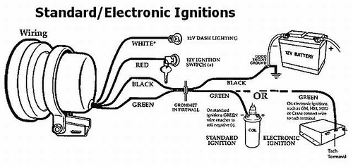
Image: www.thesamba.com
Visualizing the Connections
While the wiring diagram provides a comprehensive overview, it’s essential to physically trace the wires and confirm their connections. The diagram will guide you to the correct terminals, but it’s always a good idea to double-check the connections to ensure they match the diagram. Look for color coding, insulation markings or labels that can assist in identifying and verifying the wires.
Troubleshooting with the Wiring Diagram
Troubleshooting a malfunctioning tachometer starts with understanding the wiring diagram. If the tachometer is not functioning, check the connections at each terminal. Make sure the power supply wire is connected and receiving power, and verify that the signal input wire is properly connected to the engine’s ignition system. Also, ensure the ground connection is secure, and that the illumination wire is connected to the parking light circuit. By comparing your actual wiring to the diagram, you can quickly trace and isolate any issues.
Customization with the Autometer Sport Comp Tach Wiring Diagram
Beyond troubleshooting, the wiring diagram unlocks a realm of customization possibilities. By understanding the wiring, you can fine-tune the tachometer’s performance and appearance to match your preferences.
- Redline Adjustment: Some Autometer Sport Comp Tach models offer a redline adjustment feature. The diagram will specify a terminal that allows you to connect a resistor to change the redline setting. By using different resistor values, you can customize the tachometer to display different redline levels.
- Illumination Color: Many models include customizable illumination features. By understanding the wiring, you can replace the stock bulb with a different color to accentuate your dashboard. The wiring diagram will detail the correct terminal and bulb specifications to maintain proper functionality.
- Additional Features: Some Autometer Sport Comp Tach models may have other adjustable features, such as peak recall or a warning light. The wiring diagram will provide detailed instructions for connecting and configuring these features.
Using the wiring diagram as a guide, you can safely and effectively customize your Autometer Sport Comp Tach to enhance its functionality and aesthetics.
Tips for Using the Autometer Sport Comp Tach Wiring Diagram
The Autometer Sport Comp Tach wiring diagram is an essential tool for anyone who wants to understand, troubleshoot, or customize their tachometer. By understanding its basic components, you can gain valuable insights into the device’s operation.
Here are some additional tips for using the Autometer Sport Comp Tach wiring diagram effectively:
- Keep a hard copy: Having a physical copy of the diagram readily available is essential for convenient reference during troubleshooting.
- Use a multimeter: To verify connections, it’s helpful to have a multimeter on hand. You can use it to test the voltage at each terminal, ensuring power supply and proper grounding.
- Consult the manual: Always refer to the Autometer Sport Comp Tach manual for detailed instructions and troubleshooting tips. The manual can often provide additional insights into the wiring diagram and its interpretation.
- Be cautious with electrical systems: When working with electrical systems, always take safety precautions. Disconnect the battery before working on the wiring to prevent electrical shocks.
FAQ: Common Questions about the Autometer Sport Comp Tach Wiring Diagram
- Q: Where can I find the wiring diagram for my Autometer Sport Comp Tach?
A: You should be able to find a wiring diagram for your specific Autometer Sport Comp Tach model in the user manual, on the Autometer website, or in downloadable resources online.
- Q: What is the purpose of the signal input wire?
A: The signal input wire transmits pulsing signals from the engine’s ignition system to the tachometer. These pulses tell the tachometer how many times the engine is turning per minute (RPM).
- Q: How do I connect the tachometer to my vehicle’s ignition system?
A: The signal input wire should be connected to a wire in the engine’s ignition system. The exact connection point will vary depending on the vehicle, but it’s typically the ignition coil or the distributor. Consult the wiring diagram and your vehicle’s owner’s manual for proper placement.
- Q: Is it safe to modify the tachometer’s wiring?
A: Modifying the wiring should only be attempted by those with a good understanding of electrical systems and safety procedures. Always consult the wiring diagram and your vehicle’s owner’s manual before making any modifications.
Autometer Sport Comp Tach Wiring Diagram
Conclusion
By mastering the Autometer Sport Comp Tach wiring diagram, you unlock the secrets behind this performance-enhancing instrument. From understanding basic functions to exploring customization options, the wiring diagram provides invaluable insights into the tachometer’s operation. Remember to always prioritize safety when working with electrical systems and seek guidance from reputable sources for any modifications.
Are you ready to take your understanding of the Autometer Sport Comp Tach wiring diagram to the next level? Leave a comment below with your thoughts and experiences. Let’s keep the performance conversation going!


